

This website views at its very best in Firefox web browser, and is not available in a mobile version.
Copyright © All Rights Reserved | Built by Serif Templates


|
|
|
|
|
|
|
Whether the car you design will be an automobile car, a monorail car, a rocket sled, an airplane, a balloon with gondola, or a boat it will need wheel Effect Bones. The game engine matches the imported locations of these bones in your car to the track splines in each RCT3 track section. These splines serve as the track boundaries. Wherever your car is in respect of its location on any track section the wheel Effect Bones keep your car at the proper distance over the rail/track bed and in between the track sides. |
||||
|
|
|
|
|
|
|
In track beds or in water rides these splines usually run along the left and right edges of the Track Section. When we set a route made up of buoys in a water ride we are actually setting the track splines for the attraction. Water rides are the only tracks that may operate free- |
||||
|
|
|
|
|
|
|
While technically it is only essential to use the front wheel Effect Bones it is recommended at the beginning of your CTR car creation efforts to get into the habit of using all four wheel Effect Bones for each car. Using only the front wheel Effect Bones will result in the rear wheels of the car pitching unnaturally and pulling away from the track over lifts and during turns. All four wheel Effect Bones are essential for the correct function of advanced CTR cars so you should get accustomed to always specifying all four wheel coordinates. |
||||
|
|
|
|
|
|
|
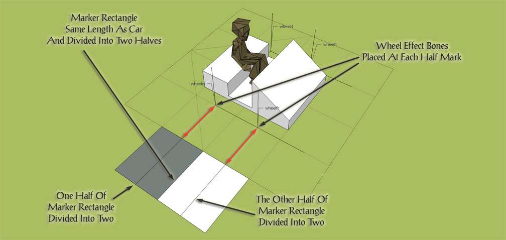
These Effect Bones should be placed scaled to the overall length of your car and their placement should be in accordance with the following method: |
||||
|
|
|
|
|
|
|
|
Imagine the base of your car is a rectangle that's been divided in half with one side of the rectangle being the front face and the other side the back face. If you divide the front face half and then the back face half into two then the ideal location to put the wheelf values is at the car front half- |
|||
|
|
|
|
|
|
|
|
|
|||
|
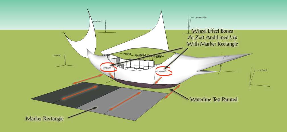
If you following this wheel Effect Bone placement method for a boat meant for a water ride you'd make the length of your marker rectangle the size of the water car where it meets the surface of the water, i.e., at the waterline We give an example here with another project on which we're working. |
||||
|
|
|
|
|
|
|
|
||||
|
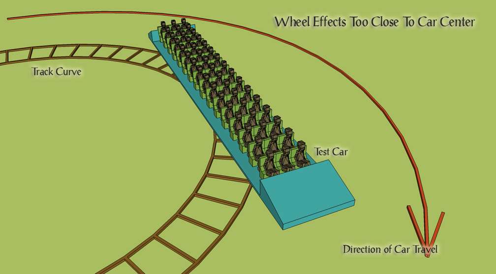
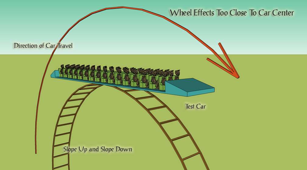
We'll now illustrate the challenges that arise when wheel Effect Bones aren't placed correctly. If we were including slopes and curves of these sizes in our custom track we'd ensure a single car would be no longer than 10 meters, or we'd import several smaller cars as a train. As it is we've deliberately made this test car some 20 meters in length to exaggerate and better illustrate the problems that will be encountered with faulty wheel bone placements. Adult male guest models have been placed in the test car to give a further idea of scale. |
||||
|
|
|
|
|
|
|
|
|
|
|
|
|
|
|
|
|
|
|
|
► |
too close to the middle of the car |
||
|
|
|
► |
will result in cars with front and back ends that overhang the outside of the track section's curve during turns. This will also give your train the appearance it's zigzagging around multiple track turns, an effect will be worse during tight turns or in a series of turns in alternating directions. |
|
|
|
|
|
|
|
|
|
|
|
|
|
|
|
|
► |
Another result is the car ends being lifted too high vertically above the track while the car is traveling over the tops of lift hills. |
|
|
|
|
|
|
|
|
|
|
|
|
|
|
|
|
|
|
|
|
|
► |
|||
|
|
|
► |
will result in cars that look like they're centring inside track turns. With the car centred inside the track section's turn arc rather than centred on the track itself it will seem to slither about the track instead of following it. Again this is particularly noticeable during tight turns. |
|
|
|
|
|
|
|
|
|
|
|
|
|
|
|
|
► |
This will also result in cars with vertical positions that are too low on the track while traveling over the tops of lift hills. In extreme cases the track apex will be visible above the floor inside the car which goes some way towards explaining why the design of some of the in- |
|
|
|
|
|
|
|
|
|
|
|
|
|
|
|
|
|
|
|
|
These images also show the effects of making cars that are too long for the curves and slopes that come with your chosen track, so as you see it's important both for the car to be an appropriate length for the curves and slopes of the track you've chosen in addition to the car having its wheel Effect Bones placed correctly. |
||||
|
|
|
|
|
|
|
|
|
|
|
|
|
|
► |
The wheel Effect Bones should be considered as anchored on Z=0 both in your modeler and at the level where they follow the shape of individual track pieces in RCT3. In your modeler, they may be moved along the Y and along the Z axis but wherever they are along X and Y they will always Import at Z=0. They are the 'parent' bones from which all other bones and your car model are based. If after checking the position of your car in the game you find the car needs to be risen, say, 10cm, then you'll raise the car model and all the Effect Bones by 10cm and leave the four wheel Effect Bones at Z=0. In this example you will find when returning to RCT3 that the car and all its other effects have risen the desired 10cm above the track |
||
|
|
|
|
|
|
|
|
► |
Using the quarter mark rectangle as a placement template keeps your wheel Effect Bones in the right positions in proportion to the length of your car. A longer car only requires that you scale up your Example Rectangle and make your re- |
||
|
|
|
|
|
|
|
|
|
|
|
|
|
Before deciding on the size of the car we'd like to model, one should know beforehand which turns come with the track that will be chosen. A single car that's too long for the size of the turns that come with the track may be divided into two in your modeler with the second half entered into the WagenDaten_ as the next consecutive car type, and then the space between the two cars given an articulation. It may be given a pivot if desired but a pivot will suggest a second separate car while an articulation suggests a single car that's been extended into two parts. Cars that are built too long for the turns that come with the chosen track type will give the same effect as wheels that have been placed close to the middle of the car. |
||||
|
|
|
|
|
|
|
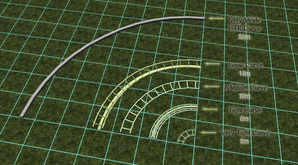
An excellent rule of thumb to follow is that the smallest of the track curve pieces upon which your cars travel should be 1½ times or 150% the length of your car. For example, if your car is 10m you'd need to be sure the track you wish to place it upon includes curves no smaller than the 14m curve. |
||||
|
|
|
|
|
|
|
|
||||
|
|
||||
|
One might also first choose the track they'd like to have and then use the curves and slopes that come with the desired track to determine the size of the cars that will be designed. |
||||
|
|
|
|
|
|
|
|
|
|
|
|
|
Each camera position and set- |
||||
|
|
|
|
|
|
|
|
||||
|
|
|
|
|
|
|
|
|
This is the location of the front camera of each car. Ideally it will include the inside of the car and some or most of the passengers who are riding it so this camera should be placed so it gives a view from inside the rear of the car as if you are a passenger in the rear of the car looking forwards out the front of the car. This Effect Bone should be placed above the peeps' heads and below the car ceiling (if your car has a roof). There are instances where this camera should be placed outside the car to the left or to the right, e.g., if the car is a steam train engine and there are front window frames and a smokestack preventing an unobstructed camerafront view. In multiple car trains, while playing RCT3 camerafront allows us to choose from which car in the train we want to POV. |
||
|
|
|
|
||
|
|
|
The view of this camera is orientated from the X+Y+Z=0 position in the car model and displays the view from the track as opposed to following the position of the car so if it is placed too far back in the car the camera view will appear to be focused on the landscape while the car gives the appearance it's sliding into and out of view from side to side as it navigates turns on the track which will result in wildly swinging camerafront views. While this does give a good impression that you're getting a POV from a guest who's looking out one side of the car and then out the other, if you don't want this effect, for cars approaching fifteen meters in length camerafront should be closer to X+Y+Z=0 than it is to the car's rear. One should avoid placing this camera ahead of X+Y+Z=0 (any minus X coordinate). |
||
|
|
|
|
||
|
|
|
For cars approaching fifteen meters, if camerafront is placed too far back along the car it won't give a view along the inside of the car but will simply default to a view from the front of the car as if it's another nosecamera. |
||
|
|
|
|
||
|
|
|
Custom Spinning Coaster cars and Robotic Coaster cars result in wildly swinging camerafront views and will require specific flagging of the CameraLATiltfactor and CameraLookahead fields in the WagenDaten_. |
||
|
|
|
|
|
|
|
|
||||
|
|
|
|
|
|
|
|
|
The placement for the rear camera in each car is based on this effect point. The best view from this camera is placed so that it looks along the inside of the car towards the rear, above the guests' heads and below the ceiling. If your car has a top and sidewalls and the rear wall isn't a window this camera effect will need to be placed above your car or a little outside the car to one side. When this bone has been set up correctly it gives a pleasing view of where the car's been. In multiple car trains camerarear allows us to choose from which car in the train we want to POV. |
||
|
|
|
|
||
|
|
|
In order to get this camera to face rearwards, while importing your car you need to give this Effect Bone a 180° RotZ adjustment in the Edit Animated Model Settings>Matrix Editor dialog. |
||
|
|
|
|
||
|
|
|
One good thing about this camera view is that it is orientated from the camera's location instead of from the car's X+Y+Z=0 coordinate, and unlike camerafront, as the car is taking the track curves this camera view is always down the center of the car out the back with the horizon gently slides sideways into and out of view of the camera. Because of this and taking into account the 180° RotZ adjustment, camerarear may be placed as far forward in the car as you like. |
||
|
|
|
|
|
|
|
|
||||
|
|
|
|
|
|
|
|
|
If you were lying belly down on the hood of a moving automibile with your head propped up on your elbows and enjoying the view forwards (a- |
||
|
|
|
|
|
|
|
As already mentioned, the WagenDaten_ permits two additional camera settings. They are |
||||
|
|
|
|
|
|
|
|
► |
CameraLookahead, and |
||
|
|
► |
CameraLATiltfactor. |
||
|
|
|
|
|
|
|
|
||||
|
|
|
|
|
|
|
|
|
Working in conjunction with CameraLATiltFactor this flag determines the gentleness or intensity of the roll in CameraLookahead. Although this flag applies only to camerafront, entering too large a value for this flag will result in a look behind camera that's just like camerarear. |
||
|
|
|
|
|
|
|
|
||||
|
|
|
|
|
|
|
|
|
Also known as Camera Lookahead Roll Factor. This flag determines the amount of X- |
||
|
|
|
|
|
|
|
|
|
|
|
|
|
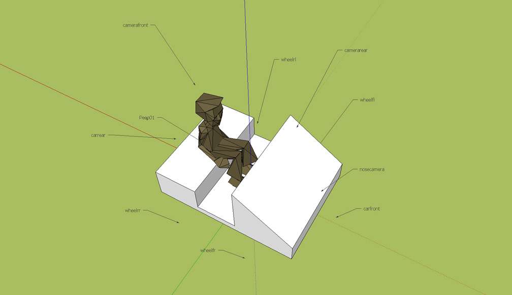
At the end of this series of sessions, included in our downloads is our basic car model SKP complete with our recommended basic set of effect bones as shown. |
||||
|
|
|
|
|
|
|
|
||||
|
|
|
|
|
|
|
Just like with CSO's, car models can be painted with any suitable texture whether that texture is a solid color or a photo- |
||||
|
|
|
|
|
|
|
Transparent textures, masked textures, and texture styles, such as reflectivity and specularity may be successfully imported with car models. |
||||
|
|
|
|
|
|
|
Final textures should only be painted on our cars when we've given them a trial in the game and are completely satisfied with the car size, shape, its proportions, and are happy with how our park guests interact with it. Until that time it is recommended to paint car models with solid test color swatches. |
||||
|
|
|
|
|
|
|
|
|
|
|
|
|
Most textures entered into the Importer's Create OVL dialog will default as having an internal alpha. Textures that don't require transparency that are entered into the Create OVL dialog with the internal alpha default will be considered as an alpha texture by CTR Creator even if they are not actually transparent. Such an oversight will reduce the number of actual transparencies that you may use with CTR Creator. Do ensure that textures are not listed as alphas unless you specifically require transparency with the texture. |
||||
|
|
|
|
|
|
|
We didn't extensively test this but from our regular use of CTR Creator v1.0 it appears there is a limit of around three alphas and some ten textures allowed. The upper limit for polys for this version of CTR Creator is 2,800. CTR Creator v0.95 seems to have these same limitations. |
||||
|
|
|
|
|
|
|
CTR Creator v0.85 has a greater tolerance for numbers of textures, alphas, and polys. It beautifully imports quality cars that will choke v0.95 and v1.0. |
||||
|
|
|
|
|
|
|
|
|
|
|
|
|
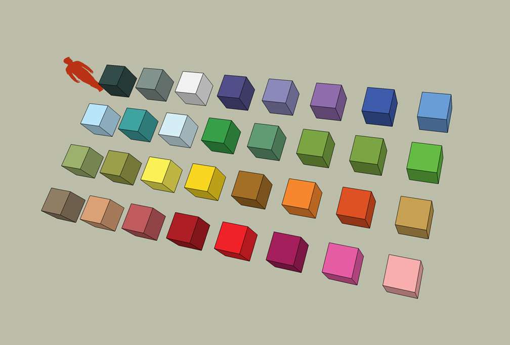
Many of us have discovered the hard way that the colors and textures that come with SketchUp's palette are in an SKM (SketchUp Material) format. This format marks these textures as files for use only with SketchUp. Additionally, any textures we have ourselves saved through SketchUp's user interface for our own use later will also save as SKM's. The SKM format is not recognized by Photoshop nor by most other image editing applications and can't be later exported for our own use whether we want to use these textures through the Importer, Path Creator or CTR Creator. Our community has little use for textures used in SketchUp that we can't use elsewhere which is why we've created this Paint Box of colors. |
||||
|
|
|
|
|
|
|
These individual, solid- |
||||
|
|
|
|
|
|
|
|
||||
|
They are topical and relevant to our community, will be fun to use, and are being presented to the community for those times when we need to be quick with our creativity so as to make it easier to get basic models ready for Importing without relying on SketchUp's palette or taking too much trouble to come up with swatches that can actually be Imported. |
||||
|
|
|
|
|
|
|
|
||||
|
|
|
|
|
|
|
Returning to our project, we're now at the stage where we're Importing our basic model only to check placements in the game which means the paint may simply be thrown on multiple faces at a time and the painting done whether the faces are grouped or not. By the way this represents the only time we may use the paint bucket in this carefree manner to throw paint in a solid color all over our model in one fell swoop and still have the textures on our model successfully Import for our needs. |
||||
|
|
|
|
|
|
|
For those who want a painting experience with a little more to it we've put all the swatches into a single 256 x 256 map. There the swatches are arranged in the same order that they appear in the game. They will require placement on your model one ungrouped face at a time, the method that's more in line with how you'll later need to apply your actual textures onto your finished model and is the method used by anyone who Imports completed work with textures that are made up of more than a single solid color. |
||||
|
|
|
|
|
|
|
Of course, each of the actual textures you select for painting your finished models will require larger sizes with more detail, depth, and contrast than that provided by these solid test model swatches. |
||||
|
|
|
|
|
|
|
Color swatches are usually placed in a folder named Materials inside the My Documents directory where all our other SketchUp files are stored. The RCT3 Color Swatch Paint Box is included in CTR Creators' Pack, the link to which is at the end of this article. |
||||
|
|
|
|
|
|
|
Drag the above toggle to a convenient place on your screen. |
|
|
|
|
The Ultimate CTR Creator


| Viewing Full-Sized Images On This Website |
| Effective Park Design: The Best Start For Your Park, Page 2 |
| Master Maps And Guest AI, Page 2 |
| Guest Generation, Park Capacity, And Peep Factory, Page 2 |
| Setting Up And Switching Your Park Entrance, Page 2 |
| Theming Our Stalls & Facilities, Page 2 |
| Our VIP Blue Book, Page 2 |
| Our VIP Blue Book, Page 3 |
| Our VIP Blue Book, Page 4: Spot The VIP's |
| Volitionist's RCT3 Animal Care Guide, Page 2 |
| Volitionist's RCT3 Animal Care Guide, Page 3 |
| Volitionist's RCT3 Animal Care Guide, Page 4 |
| How To Unlock All Campaign Scenarios, Page 2 |
| The Care And Feeding of Custom Downloads, Page 2 |
| The Care And Feeding of Custom Downloads, Page 3 |
| The Care And Feeding of Custom Downloads, Page 4 |
| RCT3 Cheats & Unlockables, Page 2 |
| Options.txt Flags, Page 2 |
| Options.txt Flags, Page 3 |
| RCT3 Keyboard & Mouse Controls: Advanced |
| RCT3 Keyboard & Mouse Controls: Freelook |
| RCT3 Keyboard & Mouse Controls: Isometric |
| RCT3 Keyboard & Mouse Controls: Normal |
| Guests Departing The Station But Not Returning |
| Guests Knocked Over |
| People Spilling Down Stairs |
| Lost Staff |
| ReAppearing Invisible Vendors |
| Park File Thumbnails |
| RCT3 Freezes |
| Earthquakes and Plumbing |
| The Importer |
| SketchUp |
| Reviewing RCT3’s History, Page 2 |
| Chris Sawyer, Page 2 |
| Showcase!: Fall 2020, TNS Pool Paths & TNS Pool Terrain, Page 2 |
| Showcase!: Fall 2020, TNS Pool Paths & TNS Pool Terrain, Page 3 |
| Showcase!: Fall 2020, TNS Pool Paths & TNS Pool Terrain, Page 4 |
| Showcase: Spring 2019 - DasMatze's Fences & Railings, Page 2 |
| Showcase: Spring 2019 - DasMatze's Fences & Railings, Page 3 |
| Showcase: Spring 2019 - DasMatze's Fences & Railings, Page 4 |
| Showcase: Fall 2018 - L-33/Lee, Page 2 |
| Showcase: Fall 2018 - L-33/Lee, Page 3 |
| Showcase: Fall 2018 - L-33/Lee, Page 4 |
| Showcase: Spring 2018 - Spez Mies Wall Set, Page 2 |
| Showcase: Winter 2017 - Mr. Sion's Tiki Bar, Page 2 |
| Showcase: Fall 2017 - Polynesian Panic, Page 2 |
| Hall of Fame: Belgabor's Invisible Doodads |
| Hall of Fame: Spice's Invisible Pool CS |
| Hall of Fame: GTT's Hedge Maze |
| Hall of Fame: GTT's Glas Labyrinth |
| Hall of Fame: Joey's Park CleanUp |
| Hall of Fame: GTT's Hedge Maze, Page 2 |
| My Adventures In SketchUp |
| CSO's I Have Imported |
| TexMod Customized Add-Ins |
| My Parks |
| Videos |
| Screenshots |
| Advertisement Land |
| Intrepid: A Revolution In Design |
| Structure And Ride Supports Set |
| CSO Study: GTT’s Hedge Maze |
| Wonderland Themed Playing Card Railings |
| Architectural Chess |
| Mini Chess |
| Planters 'n' Fountains Set |
| Intrepid: A Revolution In Design, Page 2 |
| Intrepid: A Revolution In Design, Page 3 |
| Intrepid: A Revolution In Design, Page 4 |
| Structure And Ride Supports Set, Page 2 |
| Café, Update 1 |
| Path Add-Ons, Update 1 |
| Planters And Pool Fencing, Page 2 |
| Landscaping And Park Grounds, Page 2 |
| Walls, Tunnels, And Fences, Page 2 |
| Decking, Stairs, And Balustrades Set, Page 2 |
| Decking, Stairs, And Balustrades Set, Page 3 |
| CFR & CTR CSO's, Page 2 |
| CFR & CTR CSO's, Page 3 |
| CFR & CTR CSO's, Update 1, Page 1 |
| CFR & CTR CSO's, Update 1, Page 2 |
| TexMod Tutorial |
| My TexMod Skies |
| TexMod MakeOvers For My Park |
| TexMod MakeOvers For My Park, Page 2 |
| Vanguard West |
| Vanguard West: Financial Report |
| Hillside On The Lake |
| Hillside On The Lake: Financial Summary |
| A Woodland Clearing |
| Vanguard West, Page 2 |
| Vanguard West, Page 3 |
| Vanguard West, Page 4 |
| Vanguard West, Page 5 |
| Vanguard West, Page 6 |
| Vanguard West: Financial Report, Page 2 |
| Vanguard West: Financial Report, Page 3 |
| Hillside On The Lake, Page 2 |
| Hillside On The Lake, Page 3 |
| Hillside On The Lake, Page 4 |
| Hillside On The Lake, Page 5 |
| Hillside On The Lake, Page 6 |
| Hillside On The Lake: Financial Summary, Page 2 |
| Hillside On The Lake: Financial Summary, Page 3 |
| Hillside On The Lake: Financial Summary, Page 4 |
| Hillside On The Lake: Financial Summary, Page 5 |
| A Woodland Clearing, Page 2 |
| Screenshots, Page 2 |
| Screenshots, Page 3 |
| Screenshots, Page 4 |
| Screenshots, Page 5 |
| Advertisement Land, Page 2 |
| Collaborations - Custom Content |
| Collaborations - Parks |
| L-33's POE Building 4 Set |
| RCT2 Wonderland Themed CSO's |
| The Crüe |
| L-33's POE Building 4 Set, Page 2 |
| RCT2 Wonderland Themed CSO's, Page 2 |
| POE Building 4 Set Presentation Park |
| POE Building 4 Set Presentation Park, Page 2 |
| POE Building 4 Set Presentation Park, Page 3 |
| POE Building 4 Set Presentation Park, Page 4 |
| POE Building 4 Set Presentation Park, Page 5 |
| How To Use Park CleanUp, Page 2 |
| How To Use Park CleanUp, Page 3 |
| Park Admission, Ride Pricing, And EI&N, Page 2 |
| Maximizing Your Small Park's Real Estate, Page 2 |
| Park Shuttle Configurations, Page 2 |
| Elevated Coaster Stations And Access Options, Page 2 |
| Suspended Pools And Guest Access Options, Page 2 |
| Terrain Painting - Artistry In Landscaping, Page 2 |
| Terrain Painting - Artistry In Landscaping, Page 3 |
| How To Build A Great Park, Page 2 |
| Optimize Your System And Enhance Your Gaming Experience, Page 2 |
| Custom Scenery |
| TexMod ReTexture Packs |
| Miscellaneous |
| Parks, Scenarios, & Sandboxes |
| Coasters, Rides, & Attractions |
| Structure And Ride Supports - Original Concrete |
| Structure And Ride Supports - Hewn Brick |
| RCT2 Wonderland Themed Set |
| RCT2 Revival Crüe Chess |
| FTA's Invisible Stall With Invisible Vendor |
| RCT3 Launch Screen Slideshow Template |
| Dark Ride Enclosure Toppers |
